


Rain Water Harvesting System
Rainwater Harvesting/Recharging is a technology used for collecting and storing rainwater from rooftops, land surface, watersheds, or rock catchments for direct use or diverted for bore well or groundwater recharge. The collected rainwater can either be stored or it can be used for recharging the groundwater depending on the needs and other factors. Considering the problems of severe water scarcity, pollution in existing surface water bodies, and floods during rainy seasons in India; the adoption of rainwater harvesting/recharging practices is quite necessary and need of the hour.
Being a tropical – monsoonal country, India’s rains are sufficient to cater to the need of its people, if there is the judicious use of it. Rainwater harvesting/recharging does not only improve the water usage practices but rather it is also helpful in the groundwater recharge. Considering the depletion of groundwater resources due to excessive pumping of water, agricultural land replenishment of groundwater resources is also necessary.
3R of rainwater harvesting/recharging Recharge, Retain, and Reuse (3R) is one of the sustainable and environmentally friendly ways to recharge the groundwater. 3R allows you to use the catchment itself as a buffer to store water without having to apply expensive and environmentally unfriendly technical solutions.
- Recharge:Recharging water involves the application of techniques for restoring groundwater levels by letting rainwater penetrate back into the ground.
- Retain:Retaining water involves storing rainwater to ensure that the water does not flow away, but is captured in the area and made available when needed.
- Reuse:Re-using rainwater involves using of Harvested/Recharged rainwater for multiple purposes.
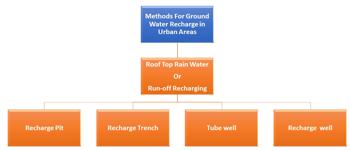
Ground water recharge in urban areas
In urban areas, rainwater available from rooftops of buildings, paved and unpaved areas can be recharged to the aquifer or utilized gainfully at the time of need. A few techniques of rooftop rainwater or surface run-off harvesting/recharging in urban areas are described below.
- Recharge pit
- In alluvial areas where permeable rocks are exposed on the land surface or are located at very shallow depth, rainwater harvesting/recharging can be done through recharge pits.
- The technique is suitable for buildings having a roof area of 100 sq.m. They are generally constructed 1 to 2 m wide and 2 to 3 m deep. The pits are filled with boulders (5-20 cm), gravels (5-10mm), and coarse sand (1.5- 2mm) in graded form. Boulders at the bottom, gravels in between and coarse sand at the top so that the silt content that will come with runoff water will be deposited on the top of the coarse sand layer and can easily be removed. The top layer of sand should be cleaned periodically to maintain the recharge rate. For smaller roof areas, the pit may be filled with broken bricks/ cobbles.
- A mesh should be provided at the roof so that leaves or any other solid waste/debris is prevented from entering the pit. A desilting /collection chamber may also be provided at the ground to arrest the flow of finer particles to the recharge pit. The by-pass arrangement is to be provided before the collection chamber to reject the first showers.
- Recharge trench
- Recharge trenches are suitable for buildings having roof area of 200-300 sq. m. and where permeable strata are available at shallow depths.
- Trench may be 0.5 to 1 m wide, 1 to 1.5 m deep and 10 to 20 m long depending upon availability of water to be recharge. These are back filled with boulders (5-20cm), gravel (5-10 mm) and coarse sand (1.5-2 mm) in graded form – boulders at the bottom, gravel in between and coarse sand at the top so that the silt content that will come with runoff will be coarse sand at the top of the sand layer and can easily be removed. The top layer of sand should be cleaned periodically to maintain the recharge rate.
- A mesh should be provided at the roof so that leaves or any other solid waste/debris is prevented from entering the trenches and a desilting/collection chamber may also be provided on ground to arrest the flow of finer particles to the trench. By-pass arrangement is to be provided before the collection chamber to reject the first showers.
- Tube wells
- In areas where the shallow aquifers have dried up and existing tube wells are tapping deeper aquifer, rain water harvesting/recharging through existing tube well can be adopted to recharge the deeper aquifers.
- PVC pipes of 10 cm dia are connected to roof drains to collect rainwater. The first roof runoff is let off through the bottom of drainpipe. After closing the bottom pipe, the rainwater of subsequent rain showers is taken through a T to an online PVC filter. The filter may be provided before water enters the tube wells. The filter is 1 –1.2 m in length and is made up of PVC pipe. Filter is divided into three chambers by PVC screens so that filter material is not mixed up. The first chamber is filled up with gravel (6-10mm), middle chamber with pebbles (12-20 mm) and last chamber with bigger pebbles (20-40 mm).
- If the roof area is more, a filter pit may be provided. Rainwater from roofs is taken to collection/desilting chambers located on ground. These collection chambers are interconnected as well as connected to the filter pit through pipes having a slope of 1:15. The filter pit may vary in shape and size depending upon available runoff and are back-filled with graded material, boulder at the bottom, gravel in the middle and sand at the top with varying thickness (0.30-0.50m) and may be separated by screen. The pit is divided into two chambers, filter material in one chamber and other chamber is kept empty to accommodate excess filtered water and to monitor the quality of filtered water. A connecting pipe with recharge well is provided at the bottom of the pit for recharging of filtered water through well.
- Trench with recharge well
- In areas where the surface soil is impervious and large quantities of roof water or surface runoff is available within a very short period of heavy rainfall, the use of trench/ pits is made to store the water in a filter media and subsequently recharge to ground water through specially constructed recharge wells.
- This technique is ideally suited for area where permeable horizon is within 3m below ground level. Recharge well of 100-300 mm diameter is constructed to a depth of at least 3 to 5 m below the water level. Based on the lithology of the area, well assembly is designed with slotted pipe against the shallow and deeper aquifer.
- A lateral trench of 1.5 to 3m width and 10 to 30 m length, depending upon the availability of water is constructed with the recharge well in the centre. The number of recharge wells in the trench can be decided on the basis of water availability and local vertical permeability of the rocks.
- The trench is backfilled with boulders, gravels and coarse sand to act as a filter media for the recharge wells. If the aquifer is available at greater depth say more than 20 m, a shallow shaft of 2 to 5 m diameter and 3-5 meters deep may be constructed depending upon availability of runoff. Inside the shaft a recharge well of 100-300 mm dia is constructed for recharging the available water to the deeper aquifers. At the bottom of the shaft a filter media is provided to avoid choking of recharge well.
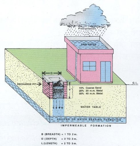
Figure 1. Recharge Pit
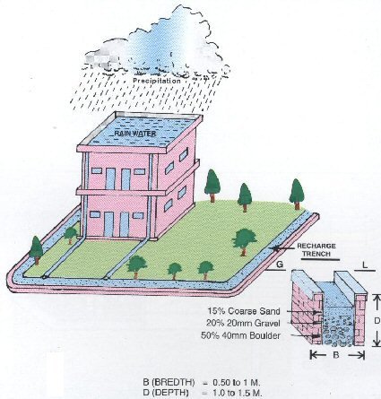
Figure 2. Recharge Trench
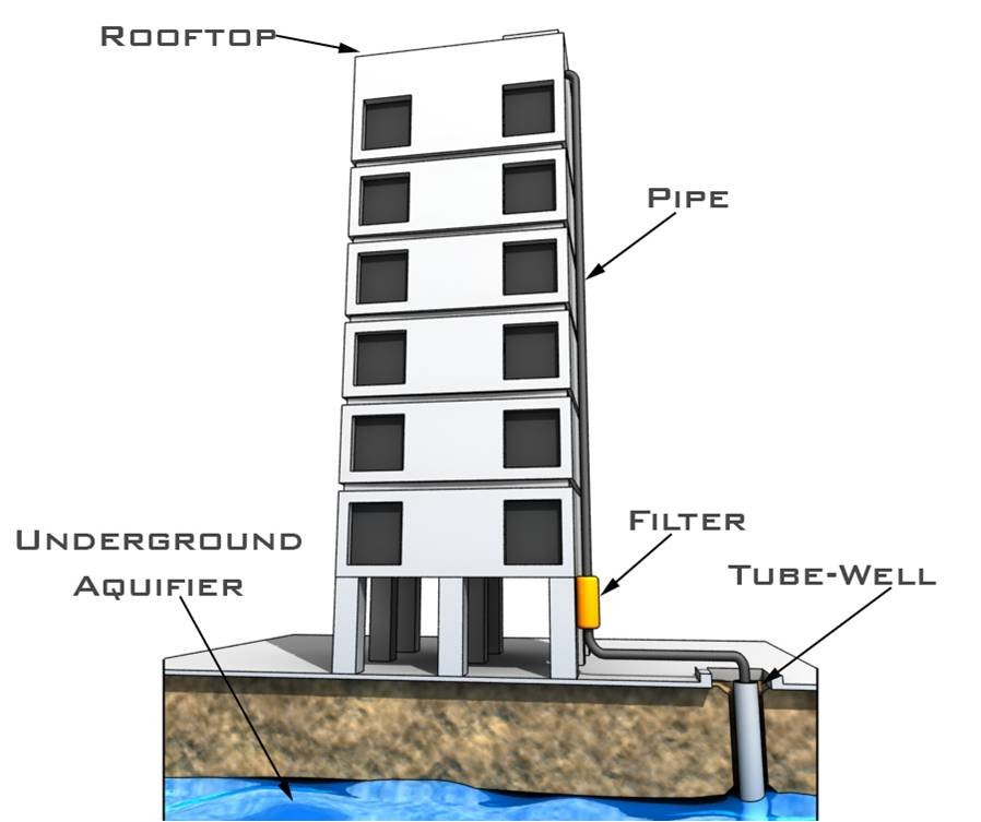
Figure 3. Tube Well
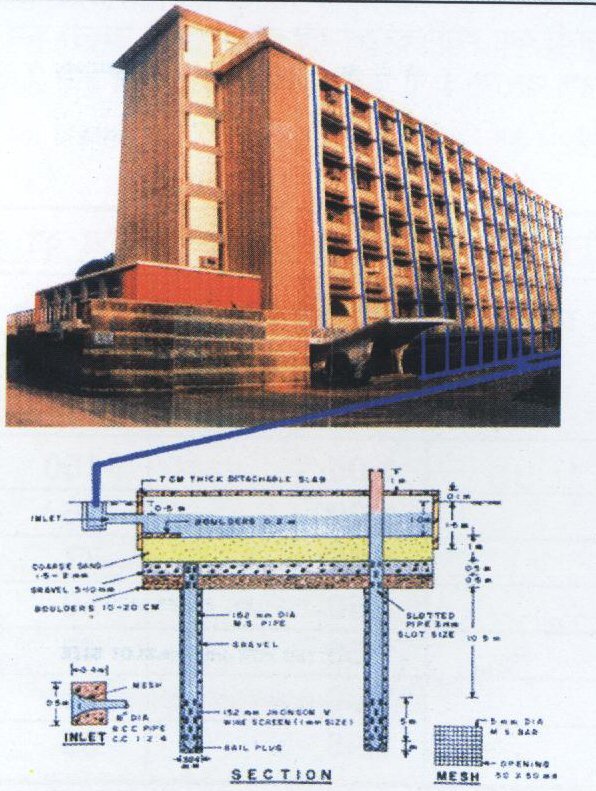
Figure 4. Trench with recharge well
Components of Roof Top Rainwater Harvesting/Recharging System (RWH)
- Catchments Area:
- Gutters (drains) and down take pipes:
- Filters and first flush devices:
- Storage tanks:
- Delivery systems:
- Recharge structures:
The area or surface which receives the rainfall is known as catchment area for rainwater harvesting/recharging. It may be rooftop, courtyard, open ground etc. In rooftop catchment, the amount and quality of rainwater collected depends on the area and type of roofing material. As per the Indian standard guidelines for rainwater harvesting/recharging, rooftop water may be collected from roofs constructed with galvanized iron sheet, aluminum sheet, deleterious glass fiber sheet, asbestos cement sheets, tiles, and slates etc. To obtain the fresh quality of water, the roofs having metallic paint or any other type of coating should be avoided. Only non-toxic paints should be used in case the water has to be collected from painted roof. Moreover, water collected from roofs painted with toxic materials should not be used for potable purposes. The catchment area should also be cleaned on regular basis to remove dust, leaves, and bird droppings so that water quality can be maintained. If the catchment area is a land surface or ground, then water can be collected in reservoirs using drain pipes. As compared to rooftop catchment, it is easier to collect rainwater from the ground surface or open area.
Gutters and down take pipes are essential for taking up the water from catchment area to the storage tanks. The materials to be used for gutters, as per the Indian standard guidelines for rainwater harvesting/recharging, are galvanized iron sheet, wood, bamboo, or reinforced cement concrete and For the construction of down take pipes, galvanized mild steel, cast iron, and high density polyethylene material may be used. The downpipe should be at least 100 mm diameter with 20 mesh (850 μ) nylon wire screen at the inlet in order to prevent dry leaves and debris from entering in it.
These devices remove grit, leaves, and dirt which are often found in the first rains. It is necessary to remove these from the water as it may contaminate the whole water of the storage tank. Sometimes, these devices are also useful when rains occur after a long time. In such conditions, the rainwater carries with it, various dissolved pollutants. Materials such as gravel, sand, or coconut, palm, or betelnut fiber, etc. may be used as filter media. Filters and first flush divert the water from the first rain to avoid mixing of it with the water of storage tank.
These tanks might be either above ground or underground or partly underground. The tank should always be covered so that water should be clean. The storage tanks may be made up of reinforced cement concrete, masonry etc. The size of the tank depends upon factors like daily demand, duration of dry spell, catchment area, and rainfall. Underground storage tanks should be suitably lined with water proofing material and preferably have a hand pump installed for withdrawal of water. Their top should remain at least 300 mm above the ground. Prior to the use of storage tank, it should be thoroughly cleaned and disinfected using chlorine, bleaching powder, and potassium permanganate etc. for periodical disinfection to prevent the growth of pathogens.
There should be efficient piping system which can deliver the stored water for the end use. In the absence of any treatment, rainwater should be avoided for the consumption and cooking. However, it can be used for other purposes. To be used for consumption, conventional water treatment is necessary. Leaking and rusted pipes should be avoided completely. To avoid any leakage, timely check-up of the pipes is necessary.
Harvested rainwater can also be used for charging the ground water aquifers through the construction of various kinds of structures like dug wells, bore wells, recharge trenches, and recharge pits. There may be different depths in recharge structures, such as depth can be such that water reaches to lower soil strata. Examples of such structures are recharge trenches, permeable pavements etc. In other case, the depth of the pipe down in the soil can be such that it reaches to the level of ground water and joins it. Examples of these kinds of structures are recharge wells. Nevertheless, for recharging the groundwater aquifers, the possibility of contamination from nearby areas should be thoroughly checked and accordingly changes may be made in the designing.
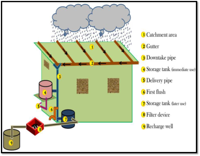
Figure 2. Components of rainwater harvesting/recharging system
Catchment area characteristics
The quantity and quality of the runoff water also depends upon the area and the type of catchment over which the rain falls and also influenced by the surface features of the catchment area. On the rough surface, the amount of water received might be less as compared to the smooth surface where large amount of water can be collected in short time. Each catchment has therefore its own runoff response and will respond differently to different rainstorm events. This particular property of each surface is represented by “runoff coefficient”. Runoff coefficient is the ratio of runoff (mm) and rainfall (mm) over a specific area.
| Roof Catchment | f | Treated Ground Catchment | f |
|---|---|---|---|
| Tiles | 0.8-0.9 | Compact and smoothened soil | 0.3-0.5 |
| Corrugated metal sheet | 0.7-0.9 | Clay/cow -dung threshing floors | 0.5-0.6 |
| Butyl rubber | 0.8-0.9 | Ground surface covering Concrete | 0.6-0.8 |
| Brick pavement | 0.5-0.6 | Untreated ground catchments Silicon-treated soil | 0.5-0.8 |
| Rocky natural | 0.2-0.5 | ||
| Soil on slopes (< 10 %) | 0.0-0.3 | Plastic sheeting (gravel covered) | 0.7-0.8 |
Availability of rain water through roof top rain water harvesting/Recharging
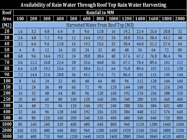
Water Harvesting/recharging potential of a site (M3) = Rainfall (MM)/1000) x Area of Catchment (M2) x Runoff coefficient
Rain Water Harvesting
Last Modified Date: 04-Jan-2020
Address
Hydraulic Engineer, Dr. Ambedkar Shopping Centre,Man-Darwaja, Ring Road, Surat- 395003, Gujarat, INDIA
+91 261 2423750-56
Helpline
Technical Helpline
![]() +91 90333 16500
+91 90333 16500